SPICE I2C Expansion Board
The SPICE I2C expansion board is a showcase design for I2C devices.
It adds sensors, memory, display, I/O expander, etc. while only using two analog signals.
The SPICE board does require 5 volts and ground for power.
This board is built to plug into an Arduino Uno. We included a standalone secondary 3.3 V power
supply to control the low voltage devices. The board can be used with any microcontroller that supports I2C. This includes Raspberry Pi, PIC and
other AVR microcontrollers, etc.
We have the following eight I2C devices on board:
- Three Axis Accelerometer
- Four LED Driver (PWM for Dimming and/or Blinking)
- EEPROM Memory - 32Kbit
- Digital Potentiometer - 5kohm
- RTCC, Real Time Clock/Calendar
- 12-bit DAC Digital to Analog Converter)
- 16-bit I/O Expander
- Temperature Sensor
Non-I2C Devices
- Voltage Regulator & Level Shift, 3.3V
- Two (2) Seven-Segment Displays
Hardware
Software
Another major element of the development was software. In choosing a broad range of devices, we created a situation where controlling everything required unique software. Controlling a 16-bit I/O expander is different from setting the output on a digital potentiometer.The most challenging was the accelerometer from Freescale. This device uses a repeat start operation that is not supported by the standard Wire library from Arduino. We found an alternate library from a great developer that does support this operation. That developer DSS Circuits has agreed to let us share their Arduino I2C library:
http://www.dsscircuits.com/articles/arduino-i2c-master-library.
For each device we will have working sample code that will include lots of comments to describe how the software works. This should give you a great starting point for developing code for your application.
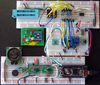
Design Process
Because I2C devices are designed to work with a microcontroller, it is natural that most of them are small surface mounted devices (SMD). This created a development situation where straight forward breadboard alone would not work. We had to first mount the devices to breakout boards and then assemble them on a breadboard to test out the operation of the device.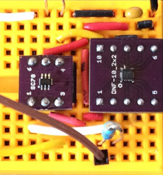
Did we mention that these parts are small? That meant the pad size and space between pads were small. Custom fabricated break out boards were going to push the boundaries of what we thought was possible. The prototype boards were not pretty, but they allowed us to verify we could use these parts before we built an expansion board around them.
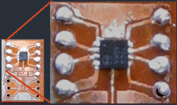
We did most of the soldering using hot air oven re-flow, but then we had to use hand soldering to fix solder bridges. It felt like an impossible task when we first tried fixing a solder bridge under the chip.
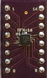
Some parts were too small to fabricate in-house PCB. The pads were too close together, e.g. QFN-16 parts had too many leads on too small a package. For these we designed breakout boards for commercial PCB fabrication. These were made at the same time as the fully designed expansion board. The plan was to test the final few parts, and at the same time be ready with a fully designed expansion board.
This was a risk, but there was simply no way to fabricate them with our equipment.
Features
Hardware and software are only part of our development efforts. Integration was an element in the selection process. We included components that operate both at 5V and at 3.3V. This requires not only a second voltage, but also level conversion for the I2C communication signals.While the Arduino board can provide the 3.3 volts, we built in the capability into the expansion board. The SPICE board can be used standalone with most other microcontrollers that have I2C capabilities.
The I2C protocol allows for all the devices on the expansion board to be controlled with only two wires. That is eight I2C devices using just two wires for control and another two wires to provide 5V and ground. You can connect even more external I2C devices using the same two analog signals.
Previously all of our projects have been launched as assembled and DIY. That is because we believe that by building it yourself you will be empowered to take on greater challenges.
This project is at the very edge of DIY. After we raise enough funds to cover the assembly cost of our projected goal, then we will begin offering this as a DIY kit. This is an advanced level kit, not recommended for beginners. See our Tindie or Amazon store for beginner or intermediate level kits.